[Book] Rootkit And Bootkit
Last Update:
Word Count:
Read Time:
Introduction
This article serves as my study notes while reading Rootkit And Bootkit.
As I continue learning about rootkits and bootkits, I will document important concepts, techniques, and case studies from the book, along with my own understanding.
The content will be continuously updated as I progress through the book.
El Libro
Reflections
I have always been interested in rootkits and bootkits. Althrough I had known about this book for quite a while, I had never seriously read it before. One of the primary reasons was that I simply did not have enough background knowledge to fully understand it.
To study this book effectively, you should already have some understanding of operating systems, especially Windows internals and APIs, because most of the rootkits and bootkits introduced in this book are closely related to the Windows operating system.
In addition, you may still feel confused even if you already have reverse engineering experience and knowledge of the aforementioned fields. This is absolutely normal because many of the techniques used by these malware families were discovered through countless experiments and investigations rather than derived directly from theory.
Therefore, I believe the best way to learn this book is to repeatedly study its content while also practically analyzing the provided samples.
Chapter 1 - What’s In a Rootkit: The TDL3 Case Study
History of TDL3 Distribution in the Wild
It was first discovered in 2010.
Controlling the Flow of Data
To fulfill their mission of stealth, kernel rootkits must modify the control flow or the data flow (or both) of the kernel’s system calls.
To do so, rootkits typically inject their code somewhere on the execution path of the system call implementation.
The Hidden Filesystem
TDL3 was the first malware system to store its configuration files and payload in a hidden encrypted storage area on the target system, instead of relying on the filesystem service provided by the operating system. Today, TDL3’s approach has been adopted by other complex threats (e.g., Rovnix Bootkit, ZeroAccess, Avatar and Gapz).
TDL3 allocates its image of the hidden filesystem on the hard disk. The image is divided into blocks of 1024 bytes each. The first block contains a file table whose entries describe files contained within the filesystem and include the following information:
- A filename limited to 16 characters, including the terminating null
- The size of the file
- The actual file offset, which is calculated by subtracting the starting offset of a file, multiplied by 1024, from the offset of the beginning of the filesystem
- The time the filesystem was created
The contents of the filesystem are encrypted with a custom encryption algorithm on a per-block basis (e.g., RC4 or XOR operation with a fixed key).
From user mode, the payload accesses the hidden storage by opening a handle for a device object named \Device\XXXXXXXX\YYYYYYYY where XXXXXXXX and YYYYYYYY are randomly generated hexadecimal numbers.
Note that the codepath to access this storage relies on many standard Windows components.
The name of the device object is generated each time the system boots and then passed as a parameter to the payload modules.
The rootkit is responsible for maintaining and handling I/O requests to this filesystem. For example, when a payload module performs an I/O operation with a file stored in the hidden storage area, the OS transfers this request to the rootkit and executes its entry point functions to handle the request.
TDL3 shows the general trend followed by rootkits. Rather than providing brand-new code for all of its operations, burdening the third-party malware developers with learning the peculiarities of that code, a rootkit piggybacks on the existing and familiar Windows functionality.
Note: This design is particularly interesting because it avoids relying on the operating system’s filesystem, making traditional file-based detection much less effective.
Chapter 2 - Festi Rootkit: The Most Advanced Spam and DDoS Bot
Compared to TDL3, Festi adopts a more modular design by introducing a plug-in architecture, allowing its functionality to be extended dynamically.
Dissecting the Rootkit Driver
The Festi rootkit is distributed mainly through a PPI scheme similar to the TDL3 rootkit. The dropper’s rather simple functionality installs into the system a kernel-mode driver that implements the main logic of the malware.
A dropper is a special type of infector. Droppers carry payload to the victim system within itself. The payload is frequently compressed and encrypted or obfuscated. Once executed, a dropper extracts the payload from its image and installs it on a victim system.
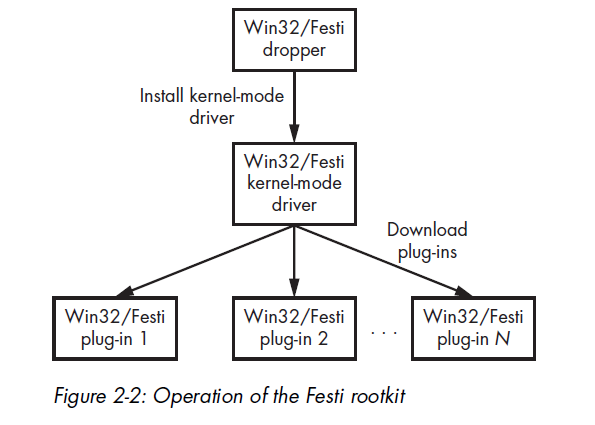
Plug-in Management
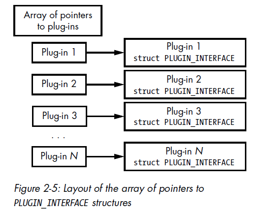
Plug-ins downloaded from the C7C server and loaded and executed by the malware. Festi maintains an array of pointers to a specially defined PLUGIN_INTERFACE structure.
1 | |
AntiDebugging Techniques
Festi also checks for the presence of a kernel debugger in the system by examining the KdDebuggerEnabled variable exported from the operating system kernel image. If a system debugger is attached to the operating system, the variable contains the value TRUE; otherwise, it contains FALSE.
Festi actively counteracts the system debugger by periodically zeroing the debugging registers dr0 through dr3. These registers are used to store addresses for breakpoints, and removing the hardware breakpoints hinders the debugging process.
1 | |
The Method for Hiding the Malicious Driver on Disk
To protect and conceal the image of the malicious kernel-mode driver stored on the hard drive, Festi hooks the filesystem driver so that it can intercept and modify all requests sent to the filesystem driver to exclude evidence of its presence.
A simplified version of the routine for installing the hook is shown below:
1 | |
The malware first tries to obtain a handle to the special system file SystemRoot, which corresponds to the Windows installation directory. Then, by executing the ObReferenceObjectByHandle system routine, Festi obtains a pointer to the FILE_OBJECT that corresponds to the handle for SystemRoot.
The FILE_OBJECT is a special data structure used by the operating system to manage access to device objects and so contains a pointer to the related device object.
The Method for Protecting the Festi Registry Key
Festi also hides a registry key corresponding to the registered kernel-mode driver using a similar method. Located in HKEY_LOCAL_MACHINE\SYSTEM\CurrentControlSet\Services, the registry key contains Festi’s driver type and the path to the driver’s image on the filesystem. This makes it vulnerable to detection by security software, so Festi must hide the key.
To do so, Festi first hooks the ZwEnumerateKey, a system service that queries information on a specified registry key and returns all of its subkeys, by modifying the System Service Descriptor Table (SSDT), a special data structure in the operating system kernel that contains addresses of the system service handlers.
The Festi Network Communication Protocol
The data is obfuscated with a simple encryption algorithm before being sent over the network. The Python implementation of the encryption algorithm is shown below:
1 | |
The malware uses a rolling XOR algorithm with a fixed 4-byte key.
Bypassing Security and Forensics Software
To send and receive packets, the malware opens a handle to the \Device\Tcp and \Device\Udp devices depending on the protocol type being used, employing a rather interesting technique to acquire the handle without drawing the attention of security software.
The most common ways for security software t monitor access to the device objects are:
- Hooking the
ZwCreateFilesystem service handler to intercept all attempts to open the devices - Attaching to
\Device\Tcpor\Device\Udpin order to intercept all IRP requests sent
Festi bypasses both techniques to establish a connection with a remote host over the network.
First, instead of using the system implementation of the ZwCreateFile system service, Festi implements its own system service with almost the same functionality as the original one.
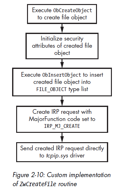
Festi manually creates a file object to communicate with the device being opened and sends an IRP_MJ_CREATE request directly to the transport driver. Thus, all the devices attached to \Device\Tcp or \Device\Udp will miss the request, and the operation goes unnoticed by security software.
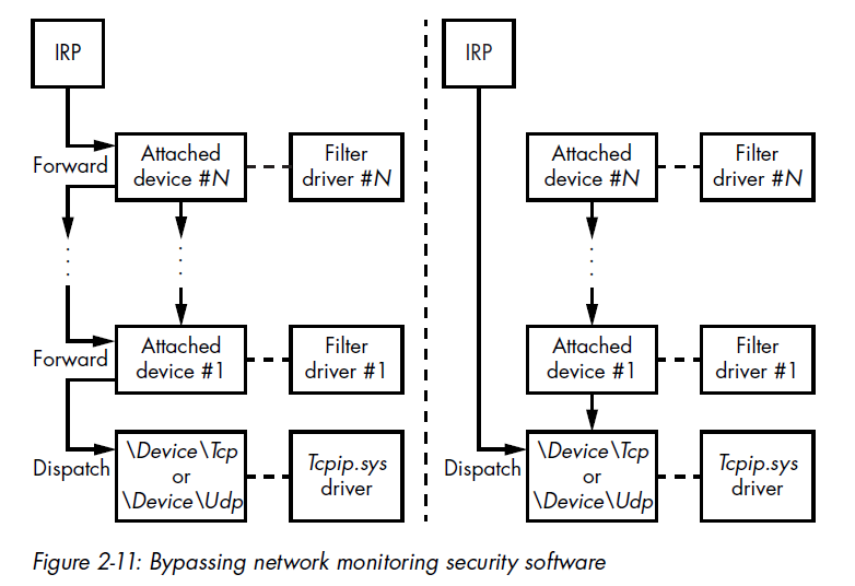
On the left side of the figure, it demonstrates how an IRP is normally processed. The IRP packet goes through the complete driver stack, and all the drivers hooked within it, including the security software, receive the IRP packet and inspect its content. The right side illustrates how Festi instead sends the IRP packet directly to the target driver, bypassing all the intermediate ones.
To send a request directly to \Device\Tcp or \Device\Udp, the malware requires pointers to the corresponding device objects. The fragment of code below shows the implementation:
1 | |
Festi obtains a pointer to the tcpip.sys driver object by executing the ObReferenceObjectByName routine, an undocumented system routine, and passing as a parameter a pointer to a Unicode string with the target driver’s name. Then the malware iterates through the list of device objects corresponding to the driver object and compares its names with \Device\Tcp and \Device\Udp.
When the malware obtains a handle for the opened device in this way, it uses the handle to send and receive data over the network. Though Festi is able to avoid security software.
Note: This highlights how powerful a malware developed by skilled authors can be.
The Domain Generation Algorithm for C&C Failure
The author implemented a Domain Generation Algorithm (DGA). It generates pseudorandom domains to make the botnet resilient to takedown attempts.
Note: In the analysis article of CryptoLocker, the author also implemented DGA for this purpose.
Malicious Functionality
Festi downloads plug-ins from C&C servers. The servers provide the plug-ins below:
BotSpam.sys: Sending spam emailsBotDos.sys: Performing DDoS attacksBotSocks.sys: Providing proxy services
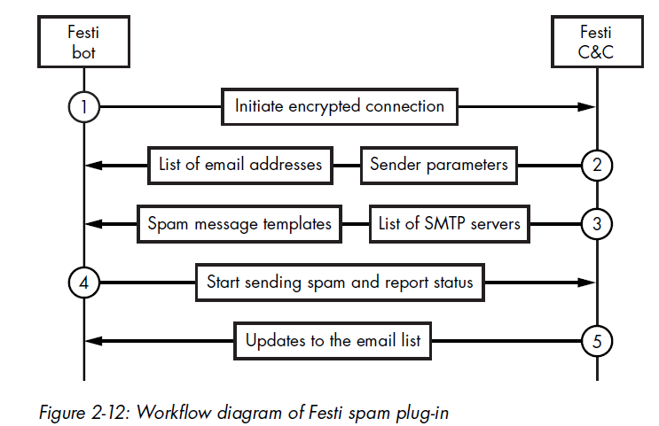
The Spam Module
The figure below shows interactions below a Festi bot and a Festi C&C server.
The DDoS Engine
The BotDos.sys plug-in allows the bot to perform DDoS attacks against specified hosts. The plug-in supports several types of DDoS attacks against remote hosts:
- TCP Flood
- UDP Flood
- DNS Flood
- HTTP Flood
Festi Proxy Plug-in
The BotSocks.sys plug-in provides remote proxy service to the attacker by implementing the SOCKS server over the TCP and UDP protocols. The SOCKS server establishes a network connection to another target server on behalf of a client, then routes all traffic back and forth between the client and the target server.
Cybercriminals may use such a service for anonymization.
Chapter 3 - Observing Rootkit Infections
“If you shame attack research, you misjudge its contribution. Offense and defense aren’t peers. Defense is offense’s child”.
Methods of Interception
The rootkit must intercept control at particular points in the operating system to prevent the anti-rootkit tools from launching or initializing. These points of interception are abundant, present in both standard OS mechanisms and non-documented ones.
In Windows, every kernel-mode driver has a dedicated entry in the system registry, located under HKEY_LOCAL_MACHINE\SYSTEM\CurrentControlSet\Services key. This entry specifies the name of the driver, the driver type, the location of the driver image on disk, and when the driver should be loaded (on demand, at boot time, at system initialization, etc.).
Rootkits frequently abuse the PsSetLoadImageNotifyRoutine routine to inject a malicious payload into the user-mode address of target processes.
Chapter 4 - Evolution of the Bootkit
From this point, this book is going to introduce bootkit.
Note: The title of “first bootkit” is usually bestowed upon Creeper, while Reaper was well-known to be the first antivirus.
Boot Sector Infectors
Boot Sector Infectors (BSIs) were among the earliest bootkits. They were first discovered in the days of MS-DOS, the non-graphical operating system that proceeded Windows, when the PC BIOS’s default behavior was to attempt to boot from whatever disk it found in the floppy drive.
The Evolution of Bootkits
The End of the BSI Era
As operating systems became more sophisticated, pure BSIs began to confront some challenges. Newer versions of operating systems replaced the BIOS-provided interrupts used to communicate with disks that had OS-specific drivers. As a result, once the OS was booted, the BSIs could no longer access BIOS interrupts and so could not infect other disks in the system.
The Kernel-Mode Code Signing Policy
Bootkit technology had to undergo major revision with the introduction of Microsoft’s Kernel-Mode Code Signing Policy in Windows Vista and later 64-bit versions of Windows, which turned the table on attackers by incorporating a new requirement for kernel-mode drivers.
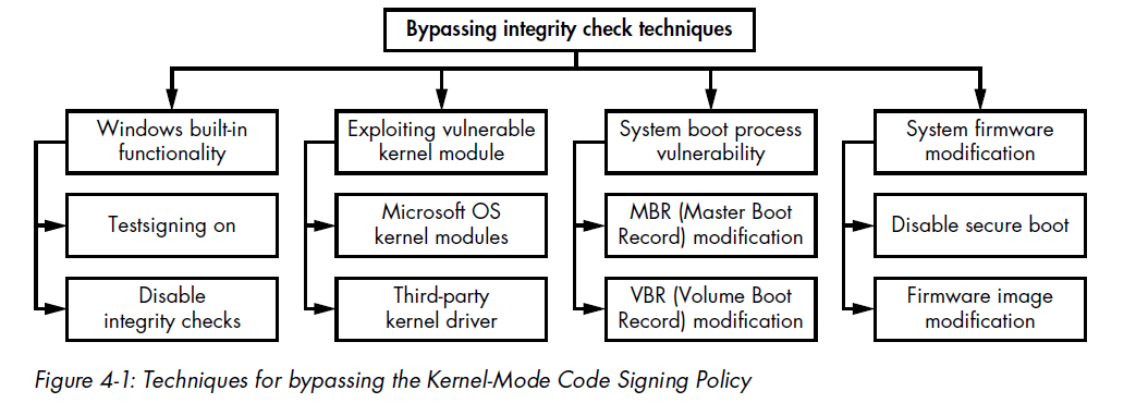
The first group operates entirely within user mode and relies on built-in Microsoft Windows methods for legitimately disabling the signing policy in order to debug and test drivers. The OS provides an interface for temporarily disabling driver image authentication or enabling test signing by using a custom certificate to verify the digital signature of the drivers.
The second group attempts to exploit a vulnerability in the system kernel or a legitimate third-party driver with a valid digital signature, which allows the malware to penetrate into kernel mode.
The third group targets the OS bootloader in order to modify the OS kernel and disable the Kernel-Mode Code Signing Policy.
The forth group aims to compromise system firmware. It attacks target firmware rather than bootloader components.
Note: In practice, the third method, compromising the boot process, is the most common, because it allows for a more persistent attack.
The Rise of Secure Boot
Today, computers increasingly ship with functional Secure Boot protection. Secure Boot is a security standard designed to ensure the integrity of the components involved in the boot process.
Just as Microsoft’s Kernel-Mode Code Signing Policy eradicated kernel-mode rootkits and initiated a new era of bootkits, Secure Boot is currently creating obstacles for modern bootkits.
Chapter 5 - Operating System Boot Process Essentials
Before diving into how bootkits are built and how they behave, it is essential to understand how the boot process works. Therefore, this chapter introduces more important bootkit-related aspects of Microsoft Windows boot process.
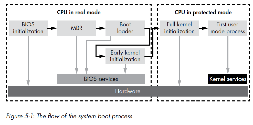
High-Level Overview of the Windows Boot Process
The figure below shows the general flow of the modern boot process. Almost any part of the process can be attacked by a bootkit, but the most common target are the Basic Input/Output System (BIOS) initialization, the Master Boot Record (MBR), and the operating system bootloader.
The Legacy Boot Process
In 1980s to 2000s, the procedure below shows how the boot process is normally executed:
- Power on (a cold boot)
- Power supply self-test
- ROM BIOS execution
- ROM BIOS test of hardware
- Video test
- Memory test
- Power-On Self-Test (POST), a full hardware check
- Test of the MBR at the first sector of the default boot drive
- MBR execution
- Operating system file initialization
- Base device driver initializations
- Device status check
- Configuration file reading
- Command shell loading
- Shell’s startup command file execution
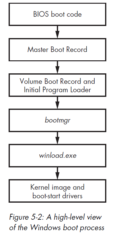
The Windows Boot Process
The figure below shows a high-level picture of the Windows boot process and the components involved, applicable to Windows versions Vista and higher. Each block in the figure represents modules that are executed and given control during the boot process, in order from top to bottom.
BIOS and the Preboot Environment
The BIOS performs basic system initialization and a POST to ensure that the critical system hardware is working properly.
The disk service is accessible through a special handler known as the interrupt 13h handler, or simply INT 13h. Bootkits will often target the disk service by tampering with its INT 13h; they do this in an effort to disable or circumvent OS protections by modifying operating system and boot components that are read from the hard drive during system startup.
The Master Boot Record
The MBR is a data structure containing information on hard drive partitions and the boot code. Its main task is to determine the active partition of the bootable hard drive, which contains the instance of the OS to load.
1 | |
Note: Total size = 0x1BE (446 byte) + 4 x ENTRY (16 byte) + 2 byte (1 SHORT = 2 byte) = 446 + 64 + 2 = 512 byte
the MBR boot code is restricted to just 446 bytes (0x1BE in hexadecimal). Next, the MBR parses the partition table, in order to locate the active partition, reads the Volume Boot Record (VBR) in its first sector, then transfer control to it.
Partition Table
1 | |
The status field signifies whether the partition is active.
The type field lists the partition type. The most common types are:
EXTENDEDMBR partition typeFAT12filesystemFAT16filesystemFAT32filesystemIFS(Installable File System used for the installation process)LDM(Logical Disk Manager for Microsoft Windows NT)NTFS(the primary Windows filesystem)
Note that a type of 0 means unused.
The fields lbaStart and size define the location of the partition on disk, expressed in sectors. The lbaStart field contains the offset of the partition from the beginning of the hard drive, and the size field contains the size of the partition.
Microsoft Windows Drive Layout
The figure below shows the typical bootable hard drive layout of a Microsoft Windows systm with two partitions.
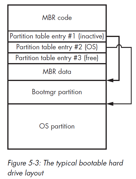
The Bootmgr partition contains the bootmgr module and some other OS boot components, while the OS partition contains a volume that hosts the OS and user data.
The Volume Boot Record and Initial Program Loader
The hard drive may contain several partitions hosting multiple instances of different operating systems, but only one partition should normally be marked as active.
The MBR does not contain the code to parse the particular filesystem used on the active partition, so it reads and executes the first sector of the partition, the VBR.
The code block below shows the layout of the VBR, which is composed of BIOS_PARAMETER_BLOCK_NTFS and BOOTSTRAP_CODE structures. The layout of the BIOS_PARAMETER_BLOCK structure is used for the specifying the volume’s filesystem. The BIOS_PARAMETER_BLOCK_NTFS and VOLUME_BOOT_RECORD structures correspond to the NTFS volume.
1 | |
1 | |
1 | |
Notice that the VBR starts with a jmp instruction, which transfers control of the system to the VBR code. The VBR code in turn reads and executes the Initial Program Loader (IPL) from the partition, the location of which is specified by the HiddenSectors field.
The layout of the VBR is summarized below:
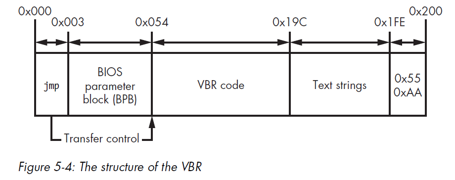
The VBR essentially consists of the following components:
- The VBR code responsible for loading the IPL
- The BIOS parameter block
- Text strings displayed to a user if an error occurs
0xAA55a 2-byte signature of the VBR
The bootmgr Module and Boot Configuration Data
The IPL reads and loads the OS boot manager’s bootmgr module from the filesystem, Once the IPL runs, bootmgr takes over the boot process.
Real Mode vs. Protected Mode
When a computer is first powered on, the CPU operates in real mode, a legacy execution mode that uses a 16-bit memory model in which each byte in RAM is addressed by a pointer consisting of two words (2 bytes): segment_start:segment_offset.
The real-mode addressing scheme allows the use of only a small amount of the available system RAM.
The bootmgr module consists of 16-bit real-mode code and a compressed PE image, which, when uncompressed, is executed in protected mode.
When winload.exe receives control of the operating system boot, it enables paging in protected mode and then loads the OS kernel image and its dependencies, including:
- bootvid.dll: A library for video VGA support at boot time
- ci.dll: The code integrity library
- clfs.dll: The common logging filesystem driver
- hal.dll: The hardware abstraction layer library
- Kdcom.dll: The kernel debugger protocol communications library
- pshed.dll: The platform-specific hardware error driver
Note: In order to read all the components from the hard drive,
winload.exeuses the interface provided by bootmgr. This interface relies on the BIOS INT 13h disk service. Therefore, if the INT 13h handler is hooked by a bootkit, the malware can spoof all data read bywinload.exe
Chapter 6 - Boot Process Security
This chapter fucuses on two important security mechanisms implemented in Microsoft Windows kernel: the Early Launch Anti-Malware (ELAM) module, introduced in Windows 8, and the Kernel-Mode Code Signing Policy, introduced in WIndows Vista.
Both mechanism were designed to prevent the execution of unauthorized code in the kernel address space, in order to make it harder for rootkits to compromise a system.
The Early Launch Anti-Malware Module
The Early Launch Anti-Malware (ELAM) module is a detection mechanism for Windows systems that allows third-party security software, such as anti-virus software, to register a kernel-mode driver that is guarateed to execute every early in the boot process, before any other third-party driver is loaded.
API Callback Routines
The ELAM driver registers callback routines that the kernel uses to evaluate data in the system registry hive and boot-start drivers.
The Windows kernel registers and unregisters these callbacks by implementing the following API routines:
- CmRegisterCallbackEx and CmUnRegisterCallback: Register and unregister callbacks for monitoring registry data
- IoRegisterBootDriverCallback: Register and unregister callbacks for boot-start drivers
These callback routines use the prototype EX_CALLBACK_FUNCTION shown below:
1 | |
The first parameter receives a context from the ELAM driver has executed one of the aforementioned callback routines to register a callback.
The second parameter provides the callback type, which may be either of the following for the boot-start drivers:
- BdCbStatusUpdate
- BdCbInitializeImage
The third argument at provides information that the operating system uses to classify the boot-start driver as known good (drivers known to be legitimate and clean), unknown (drivers that ELAM can’t classify), and known bad (drivers known to be malicious).
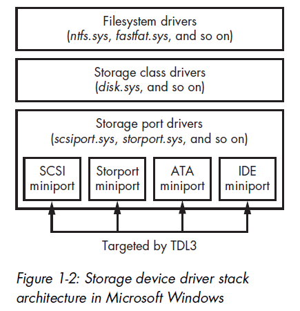
The ELAM driver does not receive the image’s base address, nor can it access the binary image on the hard drive **because the storage device driver stack is not yet initialized.
Consequently, the protection for the drivers is not very effective at this stage.
ELAM Policy
Windows decides whether to load known bad or unknown drivers based on the ELAM policy specified in registry key: HKLM\System\CurrentControlSet\Control\EarlyLaunch\DriverLoadPolicy.
| Policy Name | Policy Value | Description |
|---|---|---|
PNP_INITIALIZE_DRIVERS_DEFAULT |
0x00 |
Load known good drivers only |
PNP_INITIALIZE_UNKNOWN_DRIVERS |
0x01 |
Load known good and unknown drivers only |
PNP_INITIALIZE_BAD_CRITICAL_DRIVERS |
0x03 |
Load known good, unknown, and known bad critical drivers (default setting) |
PNP_INITIALIZE_BAD_DRIVERS |
0x07 |
Load all drivers |
How Bootkits Bypass ELAM
ELAM gives security software an advantage against rootkit threats but not against bootkits, nor was it designed to. ELAM can monitor only legitimately loaded drivers, but most bootkits load kernel-mode drivers that use undocumented operating system features.
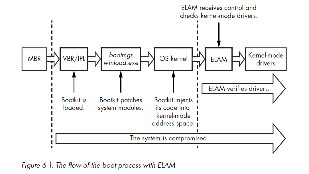
Most bootkits load their kernel-mode code in the middle of kernel initialization, once all OS subsystem have been initialized but before ELAM is executed.
Microsoft Kernel-Mode Code Signing Policy
The Kernel-Mode Code Signing Policy protects the Windows operating system by imposing code-signing requirements for modules meant to be loaded into the kernel address space.
Attackers can disable the entire logic of on-load signature verification by manipulating a few vaariables that correspond to startup configuration options.
Kernel-Mode Drivers Subject to Integrity Checks
On 64-bit systems, all kernel-mode modules, regardless of type, are subject to integrity checks.
On 32-bit systems, the signing policy applies only to boot-start and media drivers; other drivers are not checked (PnP device installation enforces an install-time signing requirement).
Location of Driver Signatures
The embedded driver signature within a PE file, such as a boot-start driver, is specified in the IMAGE_DIRECTORY_DATA_SECURITY entry in the PE header data directories.
1 | |
The Kernel-Mode Code Signing Policy has increased the security resilience of the system, but it does have its limitations.
In addition to the Kernel-Mode Code Signing Policy, Microsoft Windows has another type of signing policy: the Plug and Play Device Installation Signing Policy. It is important not to confuse the two.
System administrators can disable the PnP policy, allowing Pnp driver packages to be installed on a system without proper signatures. Also, note that the policy is applied only when the driver package is installed, not when the drivers are loaded.
The Legacy Code Integrity Weakness
The logic in the Kernel-Mode Code Signing Policy responsible for enforcing code integrity is shared between the Windows kernel image and the kernel-mode library ci.dll. The kernel uses this library to verify the integrity of all modules being loaded into the kernel address space.
The key weakness of the signing process lies in a single point of failure in this code.
In Microsoft Windows Vista and 7, a single variable in the kernel image lies at the hart of this mechanism and determines whether integrity checks are enforced. It looks like this:
1 | |
The ci.dll Module
The kernel-mode library ci.dll, which is responsible for enforcing code integrity policy, contains the following routines:
- CiCheckSignedFile: Verify the digest and validate the digital signature
- CiFindPageHashesInCatalog: Validate whether a verified system catalog contains the digest of the first memory page of the PE image
- CiFindPageHashesInSignedFile: Verify the digest and validate the digital signature of the first memory page of the PE image
- CiFreePolicyInfo: Free memory allocated by the functions
CiVerifyHashInCatalog,CiCheckSignedFile,CiFindPageHashesInCatalogandCiFindPageHashesInSignedFile - CiGetPEInformation: Create an encrypted communication channel between the caller and the
ci.dllmodule - CiInitialize: Initialize the capability of
ci.dllto validate PE image file integrity - CiVerifyHashInCatalog: Validate the digest of the PE image contained within a verified system catalog
The routine CiInitialize is the most important one.
1 | |
The CiInitialize routine also performs a self-check to ensure that no one has tampered with it. The routine then proceeds to verify the integrity of all the drivers in the boot-driver list, which essentially contains boot-start drivers and their dependencies.
Once initialization of the ci.dll library is complete, the kernel uses callbacks in the g_CiCallbacks buffer to verify the integrity of the modules.
Defensive Changes in Windows 8
With Windows 8, Microsoft made a few changes designed to limit the kinds of attacks possible in this scenario.
First, Microsoft deprecated the kernel variable nt!g_CiEnabled, leaving no single point of control over the integrity policy in the kernel image as in earlier versions of Windows.
Windows 8 also changed the layout of the g_CiCallbacks buffer.
Note: More information on the implementation details of the
ci.dllmodule can be found at https://github.com/airbus-seclab/warbirdvm.
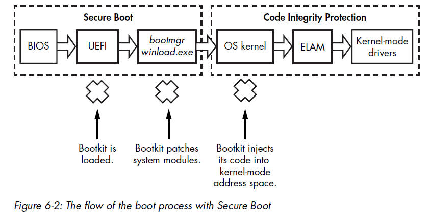
Secure Boot Technology
Secure Boot technology was introduced in Windows 8 to protect the boot against bootkit infection. It leverages the Unified Extensible Firmware Interface (UEFI) to block the loading and execution of any boot application or driver without a valid digital signature in order to protect the integrity of the operating system kernel, system files, and boot-critical drivers.
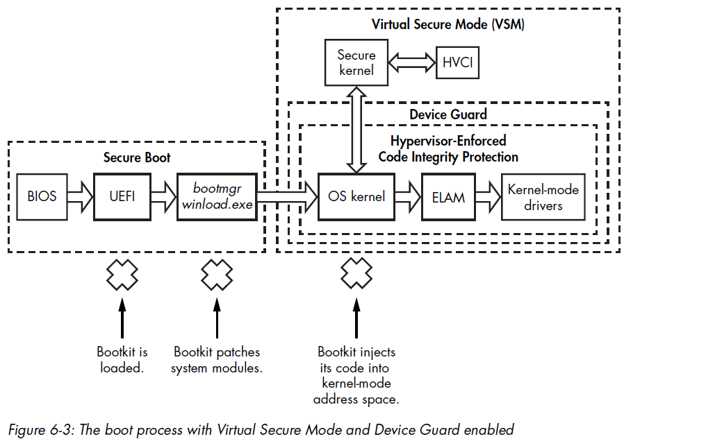
Virtualization-Based Security in Windows 10
Up until Windows 10, code integrity mechanisms were part of the system kernel itself. That essentially means that the integrity mechanism runs with the same privilege level that it is trying to protect.
To increase the effectiveness of the code integrity mechanism, Windows 10 introduced two new features:
- Virtual Secure Mode
- Device Guard
Both of which are based on memory isolation assisted by hardware. This technology is generally referred to as Second Level Address Translation, and it is included in both Intel (Extended Page Tables, or EPT) and AMD (Rapid Virtualization Indexing, or RVI) CPUs.
Second Level Address Translation
Windows has supported Second Level Address Translation (SLAT) since Windows 8 with Hyper-V (a Microsoft hypervisor).
Hyper-V uses SLAT to perform memory management (for example, access protection) for virtual machines and to reduce the overhead of translating guest physical addresses (memory isolated by virtualization technologies) to real physical addresses.
Virtual Secure Mode and Device Guard
Virtual Secure Mode (VSM) virtualization-based security first appeared in Windows 10 and is based on Microsoft’s Hyper-V.
VSM isolation makes it impossible to use vulnerable legitimate kernel-mode drivers to disable code integrity.
Device Guard technology leverages VSM to prevent untrusted code from running on the system.
Device Guard Limitations on Driver Development
Device Guard imposes specific requirements and limitations on the driver development process, and some existing drivers will not run correctly with it active.
Chapter 7 - Bootkit Infection Techniques
This chapter targets MBR infection techniques and VBR/Initial Program Loader (IPL) infection techniques.
MBR Infection Techniques
Approaches based on MBR modifications are the most common infection techniques used by bootkits to attack the Windows boot process. Most MBR infection techniques directly modify either/both the MBR code or/and MBR data (such as the partition table).
MBR Code Modification: The TLD4 Infection Technique
TDL4 reuses the notoriously advanced evasion and anti-forensic techniques of its rootkit predecessor, TDL3, but has the added ability to bypass the Kernel-Mode Code Signing Policy and infect 64-bit Windows systems.
On 32-bit systems, the TDL3 rootkit was able to persist through a system reboot by modifying a boot-start kernel-mode driver. However, the mandatory signature checks introduced in 64-bit systems prevented the infected driver from being loaded, rendering TDL3 ineffective.
Infecting the System
TDL4 infects the system by overwriting the MBR of the bootable hard drive with a malicious MBR.
TDL4 stores the original MBR so that it can be loaded later, once infection has taken place, and the system will seemingly boot as normal.
TDL4 exploits the MS-10-092 vulnerability in the Windows Task Scheduler service to elevate its privileges. It then modifies the symbolic link \??\PhysicalDriveXX to infect the MBR.
Once all of its components are installed, TDL4 forces the system to reboot by executing the NtRaiseHardError native API.
1 | |
The code passes OptionShutdownSystem as its fifth parameter, which puts the system into a BSOD.
Note: This is also how Petya and Petya are implemented
Disabling the Code Integrity Checks
In order to replace the original version of kdcom.dll with the malicious DLL on Windows Vista and later versions, the malware needs to disable the kernel-mode code integrity checks.
Encrypting the Malicious MBR Code
The code below shows a part of the malicious MBR code in the TDL4 bootkit. Notice that the malicious code is encrypted in order to avoid detection by static analysis, which uses static signatures.
1 | |
MBR Partition Table Modification
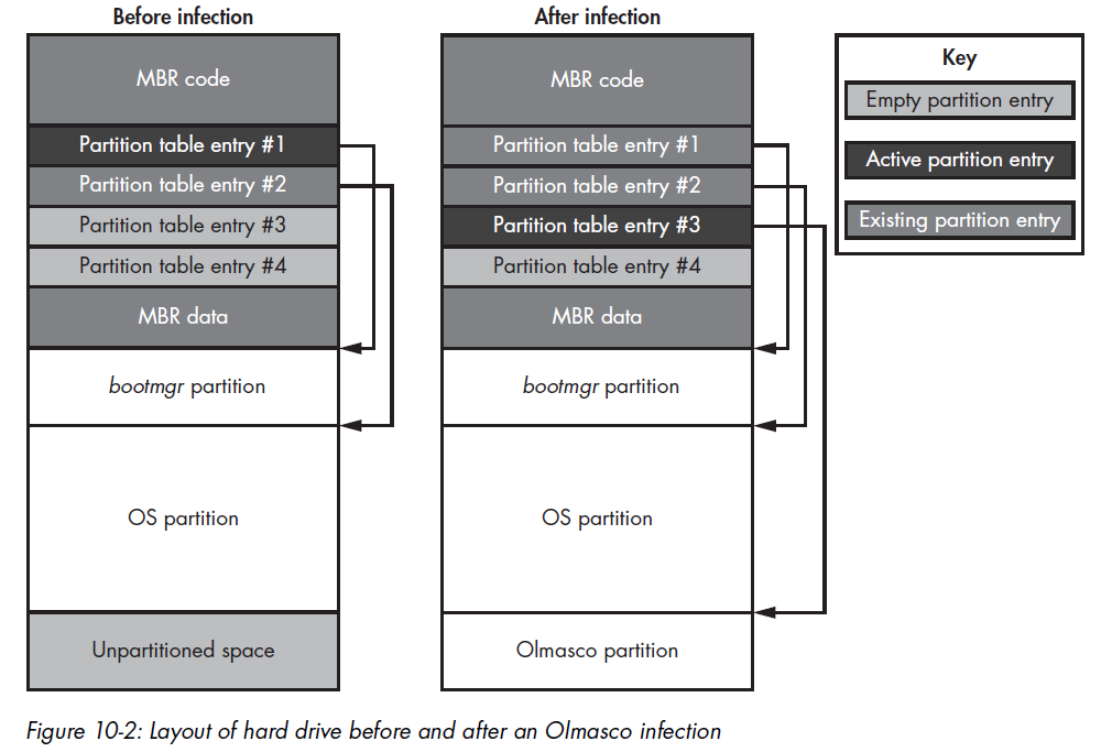
One variant of TDL4, known as Olmasco, demonstrates another approach to MBR infection: modifying the partition table rather than the MBRcode.
Olmasco first create an unallocated partition at the end of the bootable hard drive, then create a hidden partition in the same place by modifying a free partition table entry, number 2, in the MBR partition table.
This route of infection is possible because the MBR contains a partition table with entries beginning at offset 0x1BE consisting of four 16-byte entries, each decribing a corresponding partition (the array of MBR_PARTITION_TABLE_ENTRY is shown back in the image below) on the hrad drive.
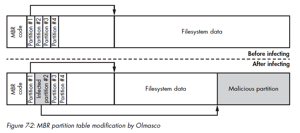
Thus, the hard drive can have no more than four primary partitions, with only one marked as active.
VBR/IPL Infection Techniques
Sometimes security software checks only for unauthorized modifications on the MBR, leaving the VBR and IPL uninspected.
All known VBR infection techniques fall into one of two groups: IPL modification and BIOS parameter block (BPB) modifications
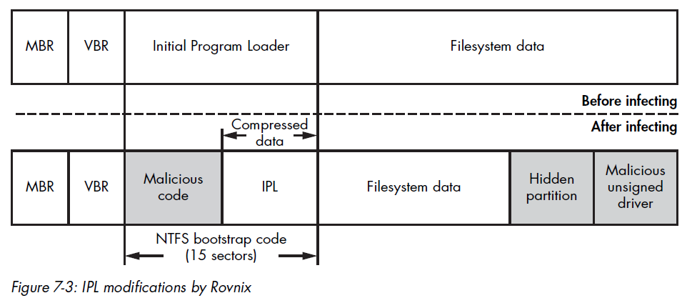
IPL Modifications: Rovnix
Instead of overwriting the MBR sector, Rovnix modifies the IPL on the bootable hard drive’s active partition and the NTFS bootstrap code.
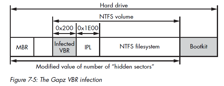
VBR Infection: Gapz
The Gapz bookit infects the VBR of the active partition rather than the IPL. Gapz is a remarkably stealthy bootkit because it infects only a few bytes of the original VBR, modifying the HiddenSectors field and leaving all other data and code in the VBR and IPL untouched.
Chapter 8 - Static Analysis of a Bootkit Using IDA Pro
This chaper introduces the basic concepts of bootkit static analysis with IDA Pro.
Analyzing the Bootkit MBR
The IDA script below decrypts the MBR code:
1 | |
Analyzing the BIOS Disk Service
Another unique aspect of the preboot environment is the BIOS disk service, an API used to communicate with a hard drive.
The BIOS disk service is accessible via an INT 13h instruction. In order to perform I/O operations, software passes I/O parameters through the processor registers and executes the INT 13h instruction, which transfer control to the appropriate handler.
The I/O operation code, or identifier, is passed in the ah register——the higher-order part of the ax register. The register dl is used to pass the index of the disk in question. The processor’s carry flag (CF) is used to indicate whether an error has occurred during execution of the service: if CF is set to 1, an error has occurred and the detailed error code is returned in the ah register.
This BIOS convention for passing arguments to a function predates the modern OS system call conventions.
This INT 13h interrupt is an entry point to the BIOS disk service, and it allows software in the preboot environment to perform basic I/O operations on disk devices, like hard drive, floppy drives, and CD-ROMs:
| Operation code | Operation description |
|---|---|
2h |
Read sectors into memory |
3h |
Write disk sectors |
8h |
Get drive parameters |
41h |
Extensions installation check |
42h |
Extended read |
43h |
Extended write |
48h |
Extended get drive parameters |
The extended operations can use an addressing scheme based on Logical Block Addressing (LBA), whereas the legacy operations rely solely on a legacy Cylinder Head Sector (CHS).
In the case of the LBA-based scheme, sectors are enumerated linearly on the disk, beginning with index 0, whereas in the CHS-based scheme, each sector is addressed using tuple (c, h, s), where c is the cylinder number, h is the head number, and s is the number of the sector.
Although bootkits may use either group, almost all modern hardware supports the LBA-based addressing scheme.
Obtaining Drive Parameters to Locate Hidden Storage
1 | |
The small size of the MBR (512 bytes) restricts the functionality of the code that can be implemented within it. For this reason, the bootkit loads additional code to execute, called a malicious boot loader, which is placed in hidden storage at the end of the hard drive.
To obtain the corrdinates of the hidden storage on the disk, the MBR code uses the exneded “get drive parameters” operation, which returns information about the hard drive’s size and geometry. This information allows the bootkit to compute the offset at which the additional code is located on the hard drive.
Examining EXTENDED_GET_PARAMS
The EXTENDED_GET_PARAMS routing is provided below:
1 | |
The only fields the bootkit actually looks at in the returned structure are the number of sectors on the hard drive and the size of the disk sector in bytes.
Reading Malicious Boot Loader Sectors
Once the bootkit has obtained the hard drive parameters and calculated the offset of the hidden storage, the bootkit MBR code reads this hidden data from the disk with the extended read operation of he BIOS disk service.
This data is the next-stage malicious boot loader intended to bypass OS security checks and load a malicious kernel-mode driver.
1 | |
In the read_loop, this code repeatedly reads sectors from the hard drive using the routine read_sector and stores them in the previously allocated memory buffer. Then the code transfer control to this malicious boot loader by executing a jmp far instruction.
1 | |
The BIOS disk service uses DISK_ADDRESS_PACKET to uniquely identify which sectors to read from the hard drive.
1 | |
Analyzing the Infected MBR’s Partition Table
The MBR partition table is a common target of bootkits because the data it contains (although limited) plays a crucial part in the boot process’s logic.
The partition table is located at the offset 0x1BE in the MBR and consists of four entries, each 0x10 bytes in size. It lists the partitions available on the hard drive, describes their type and location, and specifies where the MBR code should transfer control when it’s done.
Usually, the sole purpose of legitimate MBR code is to scan this table fro the active partition. Bootkit might be able to intercept this execution flow at the very early boot stage by simply manipulating the information contained in the table, without modifying the MBR code itself.
This illustrates an important principle of bootkit and rootkit design: if you can manipulate some data surreptitiously enough to bend the control flow, then that approach is preferred to patching the code. This saves the malware programmer the effort of testing new, altered code.
VBR Analysis Techniques
Analyzing the IPL
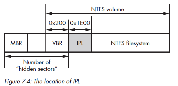
The main purpose of the VBR is to locate the Initial Program Loader (IPL) and to read it into RAM. The location of the IPL on the hard drive is specified in the BIOS_PARAMETER_BLOCK_NTFS structure.
The HiddenSectors field, which stores the number of sectors from the beginning of the hard drive to the beginning of the NTFS volume, defines the actual location of the IPL. So the VBR code loads the IPL by fetching the contents of the HiddenSectors field, incrementing the fetched value by 1, and then reading 0x2000 bytes, which correspnds to 16 sectos, from the calculated offset. Once the IPL is loaded from disk, the VBR transfers control to it.
The code below shows a part of the BIOS parameter block structure of TDL4 rootkit:
1 | |
Evaluating Other Bootkit Components
Once the IPL receives control, it loads bootmgr, which is stored in the filesystem of the volume. After this, other bootkit components, such as malicious boot loaders and kernel-mode drivers, may kick it.
Malicious Boot Loaders
Malicious boot loaders continute an important part of bootkits. Their main purposes are to survive through the CPU’s execution mode switching, bypass OS security checks, and load malicious kernel-mode drivers.
Bootkits store their boot loaders in hidden storage areas located either at the end of the hard drive, where there is usually some unused disk space, or in free disk space between partitions, if there is any.
Advanced IDA Pro Usage: Writing a Custom MBR Loader
Chapter 9 - Bootkit Dynamic Analysis: Emulation and Virtualization
This is often true for bootkits that contain encrypted components for which decryption is problematic or for bootkits like Rovnix.
Emulation with Bochs
Dynamic analysis generally relies on the debugging facilities of the platform being analyzed, but the preboot environment doesn’t provide conventional debugging facilities. Debugging in a preboot environment usually requires special equipment, software, and knowledge, making it a challenging task.
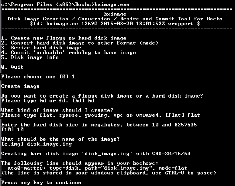
Infecting the Disk Image
The Python pseudo-code below shows how bootkit infects the disk image:
1 | |
Using the Bochs Internal Debugger
Chapter 10 - An Evolution of MBR and VBR Infection Techniques: Olmasco
In early 2011, the TDL4 family evolved into new-malware with infection tricks that had never before been seen in the wild. One example is Olmasco, a bootkit largely based on TDL4 but with a key difference: Olmasco infects the partition table of the MBR rather than the MBR code, allowing it to infect the system and bypass the Kernel-Mode Code Signing Policy while avoiding detection by increasingly savvy anti-malware software.
Chapter 13 - The Rise of MBR Ransomware
This chapter focuses on two families that have received a lot of media attention: Petya and Satana.
Ransomware with Bootkit Functionality
Instead of encrypting user files in the filesystem, Petya and Satana encrypted parts of the hard drive to make the OS unbootable and displayed a message to victims demanding payment to restore the encrypted sectors.
Petya locked users out of their systems by encrypting the contents of the Master File Table (MFT) on the hard drive. The MFT is an essential, special data structure in the NTFS volume that contains information on all the files stored within it, like their location on the volume, their filenames, and other attributes.
It is primarily used an index for finding the locations of files on the hard drive. By encrypting the MFT, Petya ensured that files could not be located and that victims weren’t able to access files on the volume or even boot their system.
Petya is capable of infecting hard drives with either MBR-based partitions or GUID Partition Table (GPT) partitions.
To infect an MBR partitioning scheme, Petya first reads the MBR to calculate the amount of free space between the beginning of the hard drive and the beginning of the very first partition. This space is used to store the malicious bootloader and its configuration information.
Petya retrieves the starting sector number of the very first partition; if it starts at a sector with an index less than 60 (0x3C), it means there’s not enough space on the hard drive, so Petya stops the infection process and exits.
The malicious bootloader of Petya consists of two components: the malicious MBR code and second-stage bootloader.
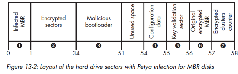
Petya combines the partition table of the original MBR with the malicious MBR code, writing the result to the very first sector of the hard drive in place of the original MBR. The original MBR is XORed with a fixed byte value 0x37, and the result is written to sector 56.
Encrypting with the Malicious Bootloader Configuration Data
Petya writes the bootloader configuration data to sector 54 of the hard drive. The bootloader uses this data to complete the encryption of the hard drive’s sectors. The code below shows how the data is generated:
1 | |
The first parameter indicates that whether the MFT of the hard drive is encrypted or not. The malware clears that flag during the step 1 of the infection process.
SalsaNonce represents the initialization value (IV) used for encrypting the MFT.
Generating Cryptographic Keys
1 | |
Generating the Ransom Key
Only the attacker should be able to retrieve the password from the ransom key, so in order to protect it, Petya uses the ECC public key encryption scheme, which is embedded in the malware.
First, Petya generates a temporary ECC key pair, known as an ephemeral key, on the victim’s system to establish secure communication with the C&C server: ecc_ephemeral_pub and ecc_ephemeral_priv.
Next, it generates a shared secret (that is, a shared key) using the ECC Diffie-Hellman key agreement algorithm. One the victim’s computer, the shared secret is computed as:
Where ECDH is the Diffie-Hellman key agreement routine.
Encrypting the MFT
Chapter 14 - UEFI Boot vs. the MBR/VBR Boot Process
This chapter focuses on the specifics of the Unified Extensible Firmware Interface (UEFI) boot process, specifically on its differences from the legacy boot MBR/VBR infection.
The Unified Extensible Firmware Interface
UEFI is a specification that defines a software interface between an operating system and the firmware. It was originally developed by Intel to replace the widely divergent legacy BIOS boot software, which was also limited to 16-bit mode and thus unsuitable for new hardware.
For compatibility reasons, some UEFI-based firmware contains a Compatibility Support Module (CSM) to support the legacy BIOS boot process for previous generations of operating systems; however, Secure Boot cannot be supported under CSM.
Differences Between the Legacy BIOS and UEFI Boot Processes
From a security standpoint, the main differences in UEFI’s boot process derive from the aim of supporting Secure Boot: the flow logic of the MBR/VBR is eliminated and completely replaced by UEFI components.
The Boot Process Flow
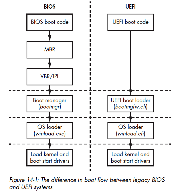
The task of MBR-based legacy BIOS was merely to apply the necessary hardware configurations and then transfer control to each succeeding stage of the boot code, from boot code to MBR to VBR and finally to an OS bootloader (e.g., bootmgr and winload.exe).
On the other hand, the boot process in UEFI is substantially different. The MBR and VBR no longer exist; instead, UEFI’s own single piece of boot code is responsible for loading the bootmgr.
Disk Partitioning: MBR vs. GPT
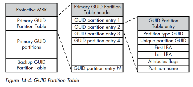
Unlike the legacy BIOS, which uses an MBR-style partition table, UEFI supports the GUID Partition Table (GPT). The GPT is rather different from the MBR. MBR tables support only four primary or extended partition slots (with multiple logical partitions in an extended partition, if needed), whereas a GPT supports a much larger number of partitions.
To support the UEFI boot process, the new GPT partitioning scheme specifies a dedicated partition from which the UEFI OS bootloader is loaded (in the legacy MBR table, this role was played by an “active” bit flag set on primary partition). This special partition is referred to as the EFI system partition, and it is formatted with the FAT32 filesystem (although FAT12 and FAT16 are also possible). The path to this bootloader within the partition’s filesystem is specified in a dedicated nonvolatile random access memory (NVRAM) variable, also know as a UEFI variable.
Note: NVRAM is a small memory storage module, located on PC motherboards, that is used to store the BIOS and operating system configuration settings.
For Microsoft Windows, the path to the bootloader on a UEFI system looks like \EFI\Microsoft\Boot\bootmgfw.efi. The purpose of this module is to locate the operating system kernel loader——winload.efi for modern Windows versions with UEFI support——and transfer control to it.
The figure below shows the boot process flow for legacy BIOS vs. UEFI, skipping those MBR and VBR steps:
GUID Partition Table Specifics
This Protective MBR prevents legacy software such as disk utilities from accidentally destroying GUID partitions by marking the entire disk space as claimed by a single partition; legacy tools unaware of GPT do not mistake its GPT-partitioned parts for free space.
How can malware developers transfer control of the boot process to their malicious code in the GPT scheme? One idea is to modify EFI bootloaders before they transfer control to the OS kernel.
How UEFI Firmware Works
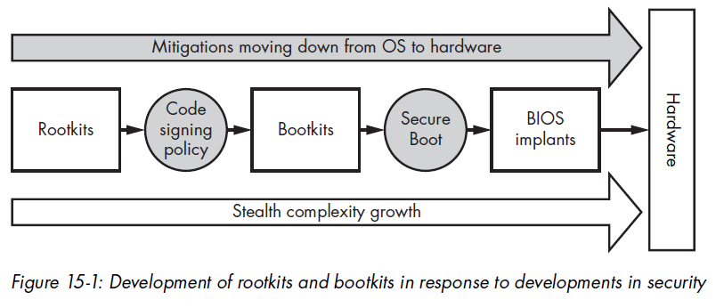
Chapter 15 - Contemporary UEFI Bootkits
The BIOS starts the initial stages for the hardware setup in the boot process, meaning the BIOS firmware level is the last boundary before hardware.
Ways to Infect the BIOS
Over the years, security researchers have identified many vulnerabilities that allow an attacker to modify the boot process with additiona malicious code. As of today, most of these have been fixed, but some hardware——even new hardware——can still be vulnerable to those old issues.
The following are different ways to infect UEFI firmware with a persistent rootkit or implant:
- Modifying an unsigned UEFI Option ROM: An attacker can modify a UEFI DXE driver in some add-on cards (used for networks, storage, and so forth) to allow malicious code execution at the DXE stage.
- Adding/modifying a DXE driver
- Replacing the Windows Boot Manager (fallback bootloader)
- Adding a new bootloader (bootkit.efi)
Chapter 16 - Contemporary UEFI Bootkits
Chapter 17 - How UEFI Secure Boot Works
Chapter 18 - Approaches to Analyzing Hidden Filesystems
Chapter 19 - BIOS/UEFI Forensics: Firmware Acquisition and Analysis Approaches
THANKS FOR READING