[Learning] OpenBootloader: Understanding Boot Process and Bootloaders
Last Update:
Word Count:
Read Time:
Background
After writing many articles for analyzing different types of malware, I realized that my understanding of low-level concepts was still limited, such as kernel for both Linux and Windows operating systems, shellcode, booting process, rootkits and bootkits. Therefore, I decided to deeply study these fields to bridge those gaps.
While doing so, I developed a simple bootloader, written in Assembly code and C. Therefore, I decided to write this article to document my findings.
Since I decided to spend more time improving my low-level knowledge, I may not post articles as frequently as before. Sorry about that!

What Is Bootloader?
Booting is the process of starting a computer, usually initiated by pressing the power button or by firmware-controlled restart logic.
Bootloader (or bootstrap loader) is a computer program that is responsible for booting a computer and an operating system. If the bootloader also provides an interactive menu for selecting different operating systems or boot options, it is often referred to as a boot manager.
Why Studying Bootloader?
Studying bootloaders is essential for understanding how bootkits (e.g., Petya) and operating systems work. In addition, it also help us understand how low-level Assembly code interacts with kernel-level programming.
OpenBootloader
OpenBootloader is a project that I implemented a simple bootloader using Assembly and C. Although this is still a simple bootloader, it demonstrates the core concepts behind multi-stage bootloading.
Approach
The full implementation is now available in this repository. Other complex features will be included in future. This article only shows partial code.
First, once the power of a machine is turned on, hardware is initialized. Hardware firstly loads the MBR (Master Boot Record) code which is located at 0x7C00 of the physical drive.
16-bit environment is adopted in this stage, so the Assembly code of the MBR code has to be implemented in NASM.
1 | |
Next, it enters the entry of booting. The data stored in the CPU has to be initialized:
1 | |
Here cli is used for avoiding interrupts while setting the stack, while xor ax, ax represents storing zero value into ax. Consequently, ds(Data Segment), es(Extra Segment), ss(Stack Segment) is also cleared. Lastly, using sti to start interrupts. The instructions cli and sti can be used for preventing bugs.
Since the size of MBR is restricted to be 512 byte. Therefore, the stage 2 load is required.
1 | |
Note this Cylinder-Head-Sector (CHS) is adopted in this case, rather than Logical Block Address.
Here the register ch indicates Cylinder 0. The register cl represents sector 2 will be used (sector 1 is the MBR). dh indicates head 0 of CHS. Finally, int 0x13 leads the system using the BIOS disk service. The specific functionality is indicated by ah, in this case, 0x02 represents “Read sectors”.
In the stage 2, we need to shift the program from Real Mode to Protected Mode because we need to use C language to implmenet more complex feature.
To do so, we need to enable the A20 line. The original Intel 8086 only had 20 address lines, allowing access to 1 MB for memory. The address is from 0x00000 to 0xFFFFF. When newer CPUs added more address lines, IBM introduced the A20 gate for backward compatibility with old DOS software.
Without A20 enabled, 0x100000 wraps around to 0x000000, which causes memory corruption. In practice, A20 must be enabled before using memory beyond 1 MB, which is typically required in Protected Mode environment.
Loading the Global Descriptor Table (GDT) is also required. Protected Mode uses descriptors instead of Real Mode segments. In Real Mode:
1 | |
However, in Protected Mode:
1 | |
The GDT defines:
- segment base
- segment limit
- access rights
- privilege levels
After doing these, the Protected Mode can be enabled by setting register CR0. Therefore, the Assembly code can be implemented below:
1 | |
This sequence:
1 | |
enabling the Protected Mode by configuring CR0 (the control register in the CPU). CR0.PE = 1 represents Protected Mode while zero value represents Real Mode.
The reason that is has to be implemented like this sophisticated method is: CR0 cannot be modified directly:
1 | |
This is prohibited and dangerous because:
- CR0 contains many important system flags.
- overwritting it would reset everything except PE bit.
- this can crash the CPU or break memory management.
Therefore, the correct method is: read -> modify -> write.
Right after enabling Protected Mode, bootloaders typically perform a far jump because
- it flushes the instruction pipeline
- loads a new code segment (GDT selector)
- completes the mode switch safely
Without this jump, the CPU may execute invalid instructions.
Eventually, the bootloader written in C can be called:
1 | |
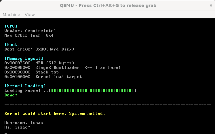
The demonstration is shown below:
Boot Flow
In conclusion, the boot process of OpenBootloader can be summarized as:
- BIOS loads the MBR into memory at 0x7C00
- Stage 1 initializes the CPU environment
- Stage 1 loads the stage 2 loader from disk
- Stage 2 enables A20
- Stage 2 loads the GDT
- The CPU switches from Real Mode to Protected Mode
- Control is transferred to the bootloader written in C
The flow chart is shown below:
THANKS FOR READING!